Page allocator
The page allocator constitutes the basic layer of the memory management subsystem in MMU architectures. It is
responsible for allocating the physical memory pages (page frames). In non-MMU architectures, the page allocator
allocates only fake page_t structures used by upper layers and plays a marginal role in memory management. This
section focuses on the role of a page allocator in MMU architectures.
Page array
The available physical memory is treated as a set of physical pages (page frames). Each physical page available is
described using the page_t structure. The structure is defined in the HAL, but upper layers assume that some
attributes are defined. The minimum set of attributes is as follows.
    typedef struct _page_t {
        addr_t addr;
        u8 idx;
        u8 flags;
        struct _page_t *next;
        struct _page_t *prev;
    } page_t;
The addr attribute stores the physical page address, the flags describe page attributes (see further sections). The
next and prev pointers and idx are used in the page allocation algorithm to construct lists of free pages.
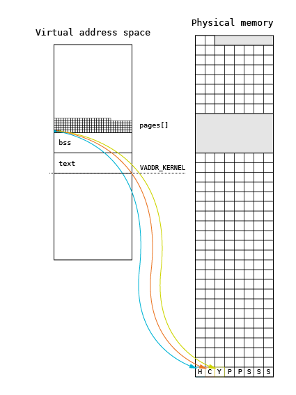
When the memory management subsystem is initialized, the _page_init() function creates an array of page_t structures
(pages[]) using the pmap_getPage() call from the HAL subsystem. This call is used to discover the page frames by
upper (hardware-independent) layers of the memory management subsystem. The page array is located at the beginning of
the kernel heap, right after the kernel BSS segment.
The memory for the structure is allocated using a heap extension. This extension is performed by using the
_page_sbrk() function, which allocates a new page from the pool using the _page_alloc()function and maps it into the
kernel address space directly with pmap_enter() at the top of the heap. Pages are allocated using a regular allocation
algorithm, but data structures used for allocation are not fully initialized. The array creation algorithm is presented
below.
    for (page = (page_t *)*bss;;) {
      if ((void *)page + sizeof(page_t) >= (*top))
        _page_sbrk(pmap, bss, top);

      if ((err = pmap_getPage(page, &addr)) == -ENOMEM)
        break;

      if (err == EOK) {

        if (page->flags & PAGE_FREE) {
          page->idx = hal_cpuGetFirstBit(SIZE_PAGE);
          _page_add(&pages.sizes[page->idx], page);
          pages.freesz += SIZE_PAGE;
        }

        else {
          pages.allocsz += SIZE_PAGE;
          if (((page->flags >> 1) & 7) == PAGE_OWNER_BOOT)
            pages.bootsz += SIZE_PAGE;
        }
        page = page + 1;
      }

      /* Wrap over 0 */
      if (addr < SIZE_PAGE)
        break;
    }
The initialization loop in each iteration discovers a new physical page using the pmap_getPage(). The function fills
the newly allocated page_t structure and returns the next valid physical address in the addr argument. The returned
page is flagged as either free or allocated using the flags attribute. The next two upper bits of this attribute
define the page ownership: a page can belong to the kernel, application or bootloader (memory reserved by BIOS on a PC
is marked in this way). The next upper bits define the page usage in the specific domain defined by ownership. For
example, pages marked as allocated by the kernel may be allocated for specific purposes (stack, heap, interrupt table,
page table etc.).
Presentation of page array during the boot process
During the kernel boot process, the page[] is presented on the screen using letters and periods. The letter
interpretation will be presented using a sample map for a PC with 128 MB of RAM.
vm: HCYPPSSS[24H][22K][103H]..B[80x][16B][32509.]BBB[101574x][64B]
In this map, the first physical page is allocated to the kernel heap. The second page is used for CPU purposes
(interrupt and exception table). The Y-marked page stores the syspage_t structure used for communication between
the loader and the starting kernel. After this page, there are two pages used for storing structures used for paging
(page directory and page table marked with P). The next pages are allocated for the initial kernel stack. They will
be released after starting the init process, switching into its main thread stack. The next characters
(in square parentheses) contain the information that next 24 pages are allocated to the kernel heap. The next
22 pages store the kernel code and data. These are followed by 103 pages allocated to the kernel heap and two
free pages (marked with periods). The B character informs that next pages are used by the bootloader (BIOS).
This page is followed by a gap (i.e. the gap after the 640 KB of address space). After the gap, there are 16
pages allocated to BIOS and 32509 free pages. At the end of the address space, there are 64 pages reserved by BIOS.
| Letter | Page Type | Description |
|---|---|---|
| . | PAGE_FREE |
Free page |
| x | Memory gap |
Memory gap |
| B | PAGE_OWNER_BOOT |
Reserved by Bootloader / BIOS |
| A | PAGE_OWNER_APP |
Used by application |
| K | PAGE_OWNER_KERNEL |
Used by kernel for unspecified reasons |
| Y | PAGE_OWNER_KERNEL \| PAGE_KERNEL_SYSPAGE |
Used by syspage_t |
| C | PAGE_OWNER_KERNEL \| PAGE_KERNEL_CPU |
Reserved for CPU specific purposes |
| P | PAGE_OWNER_KERNEL \| PAGE_KERNEL_PTABLE |
Used for paging |
| S | PAGE_OWNER_KERNEL \| PAGE_KERNEL_STACK |
Used as kernel stack |
| H | PAGE_OWNER_KERNEL \| PAGE_KERNEL_HEAP |
Used as kernel heap |
| U | UNDEFINED |
Undefined |
Page allocation
The page allocator in the Phoenix-RTOS kernel is based on a well-known buddy algorithm. The figure below shows a graphical illustration of data structures used in this algorithm.
Each square corresponds to a physical page, with the assumed page size of 4096 bytes. The main structure used in
the allocation is the sizes[] array. The size[] array is created on the basis of the page[] array during
the memory management initialization.
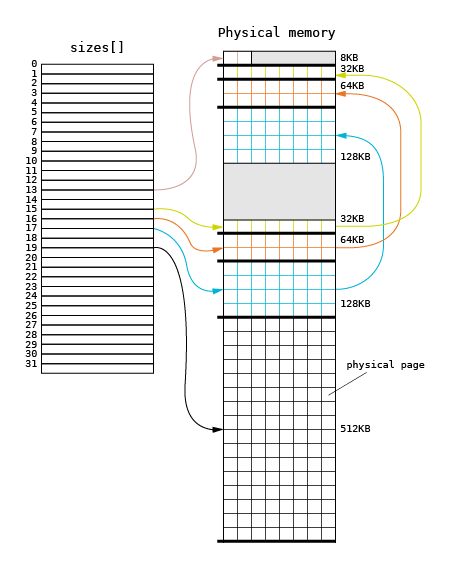
The size[] array contains pointers to lists of physically coherent sets of pages. The n-th entry of sizes[]
array points to the list of sets whose size is the n-th power of 2. For example, an entry with the 0 index points
to page sets whose size is 1 byte. An entry with the 12 index points to sets containing 4096 bytes of physical memory.
The initialization algorithm divides all accessible physical space into regions of maximum size. This means that during
the allocation process a region should be divided into smaller regions and the obtained free regions should be
added to the proper lists pointed by the size[] array.
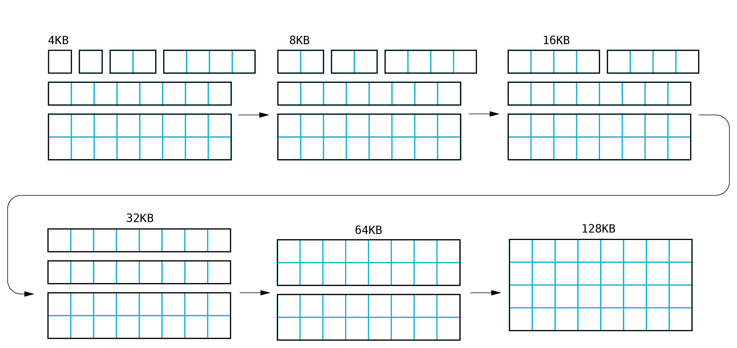
Sample allocation
Let us have a look at an allocation process where only one region of 128 KB in size is available, and 4096 bytes
should be allocated. The allocation starts with the lookup of the first region. The starting entry of size[]
array is calculated on the basis of the requested size (4096 bytes). In this case, the starting entry will be 12,
and no list is available in this entry. The lookup is performed for the next entry and finally the 128 KB region
list is found (entry 17). When the first not-empty entry is found, the algorithm proceeds to the next step, which
is illustrated below.
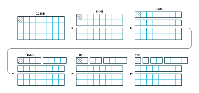
The first page set is removed from the list and divided into two 64 KB regions. The upper 64 KB region is added to the
size[16] entry and then split. The first 64 KB region is split into two 32 KB regions. The upper 32 KB region is
returned to the size[15] entry. Next, the first half of the region is divided into two 16 KB regions, and finally,
only one page is available. This page is returned as an allocation result. The complexity of this allocation is
O(log2N). The maximum number of steps that should be performed is the size of size[] array minus
the log2(page size). The maximum cost of page allocation on a 32-bit address space is 20 steps.
Page deallocation
Page deallocation is defined as the process opposite to the page allocation process.
Sample deallocation
Let us assume that the page allocated in the previous section must be released. The first step is to analyze the
neighborhood of the page based on the pages[] array. The array is sorted, and it is assumed that the
next page for the released page_t is the page_t structure, describing the physical page located right
after the released page or the page located on higher physical addresses. If the next page_t structure describes
the neighboring page, and if it is marked as free, the merging process is performed. The next page is removed from
the sizes[] array and merged with the page which should be released. If the region created in this way is located
right before the free region of the same size, the merging process is repeated. The next steps are repeated forming
larger regions until there are no free neighboring regions.
Page allocation for non-MMU architectures
In non-MMU architectures, the page_t structure is only allocated as needed by upper layers (i.e. a memory mapper).
It does not correspond to a real memory segment. During the kernel initialization, a pool of page_t structures is
created, assuming a given page size. The number of page_t entries is proportional to the size of physical memory.
    void _page_init(pmap_t *pmap, void **bss, void **top)
    {
        page_t *p;
        unsigned int i;
        pages.freesz = VADDR_MAX - (unsigned int)(*bss);
        ..
        /* Prepare allocation queue */
        for (p = pages.freeq, i = 0; i < pages.freeqsz; i++) {
                p->next = p + 1;
                p = p->next;
        }
        (pages.freeq + pages.freeqsz - 1)->next = NULL;
        ..
    }
The assumed page size depends on the architecture and the available memory size. For microcontrollers with small memory sizes, the page size is typically 256 bytes.
Page allocation is quite simple. It just retrieves the first page_t entry from the pool. In the deallocation process,
a page_t is returned to the pool. It must be noted that the real memory allocation is performed during the memory
mapping process. All processes and the kernel use the same, common memory map which stores all segments existing in
the physical memory.